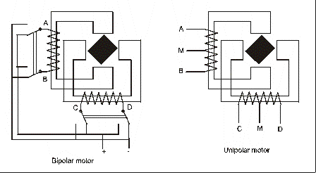
As in a dutch phrase:" More then one road lead to Rome!" There are a lot of ways! For those who don't have any idea how to do this, check the following. Steppermotors rotate in steps by pulses from a supply. By my knowledge there are two types; Bipolar and Unipolar. (see schematic below)
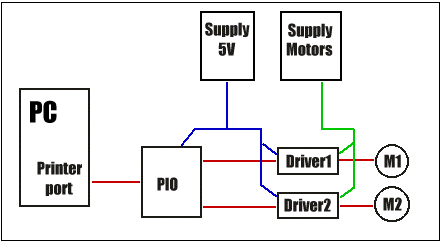
With Bipolar motors the supply need to be turned around to get the steps going in the other direction. Unipolar motors has sepparate coils for each direction. Also the steppingrate per cycle can variate. I used 200 steps/cycle motors but there are more types. To let a motor step is a quite complex thing so I just give you some info on the drivers I used. The driver is a controller between the PIO and the motor. (see below)
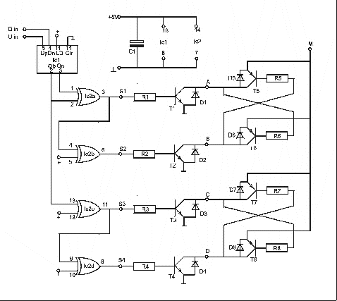
It can create a much easyer way to puls the motor and it can controll the high current for the coils. The schematic of the drivers I used is below. Click on it to get a good wide view of the drawing!
For a Bipolar motor you will need the whole circuit. For a Unipolar motor only the left side of the circuit till the A-B-C and D connections is used. Together with M, they are connected to the motor. + Means +5V Needed for one driver:
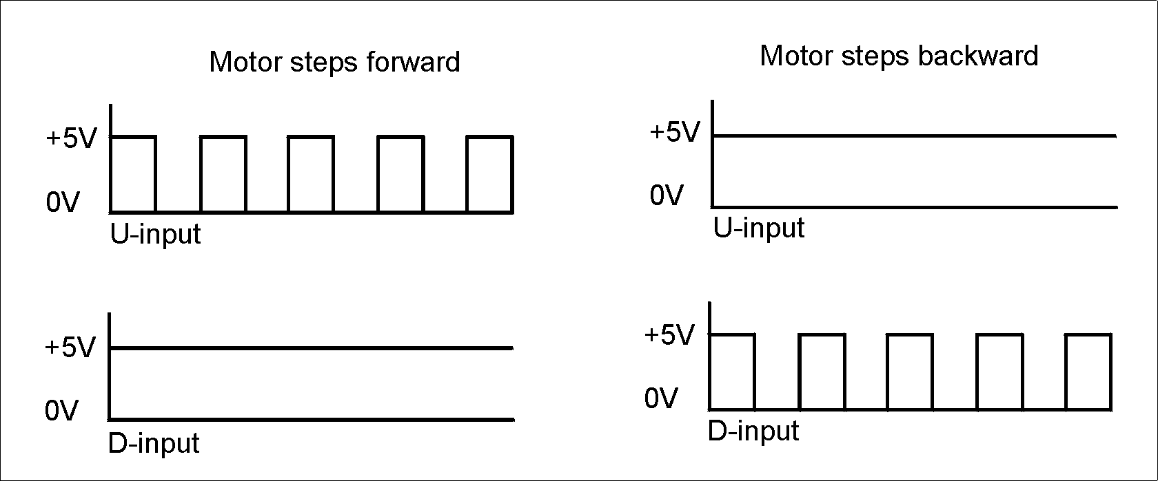
The Uin and Din connections are to be connected to the PIO. By changing the level of these lines, the motor steps forward or backwards. (see below)
I wrote a small basic routine wich runs in PowerBASIC, or with a small adjustment, with QBASIC. It can plot HPGL files. Click here to download! |